Main Product
Our company's products are widely sold in multiple countries
Rubber tyred gantry cranes travel on rubber tyres and can move flexibly between yard areas. They are often used for precast components, steel structures, containers, and heavy materials. Unlike rail-mounted gantry cranes, they need no fixed rails and offer flexible relocation. However, they require higher ground bearing capacity and more turning space. Different cargo types, site conditions, and lifting needs require different structures. These include single-beam, double-beam, A-frame, and container-specific designs. This article reviews main structure types and selection factors. It explains their differences and applicable scenarios. This helps users set a safer configuration direction in early project stages.
Looking for Rubber Tyred Gantry Cranes for Your Site?
Whether you need single-beam, double-beam, or A-frame rubber tyred gantry cranes, HSCRANE can customize a solution. We match your capacity, span, lifting height, and cargo type.
[Get Your Custom Rubber Tyred Gantry Crane Solution]
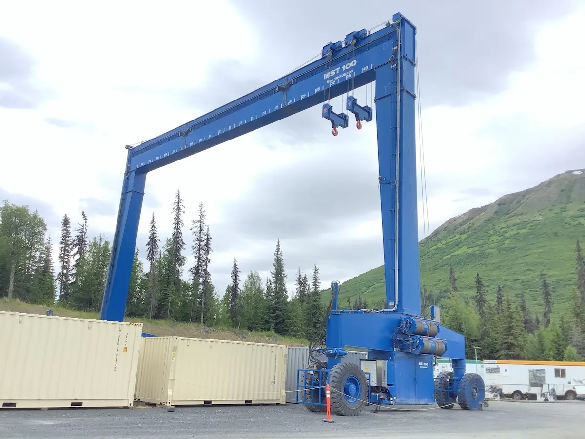
The classification of rubber tyred gantry cranes reflects different arrangements of load paths. Single-beam units concentrate load on one main girder. Double-beam units share load between two main girders. A-frame units spread force more evenly to the foundation through leg geometry. Container-specific units optimize gantry clearance and spreaders. The following four sections explain these types. When selecting, first check capacity and span ranges, then review details.
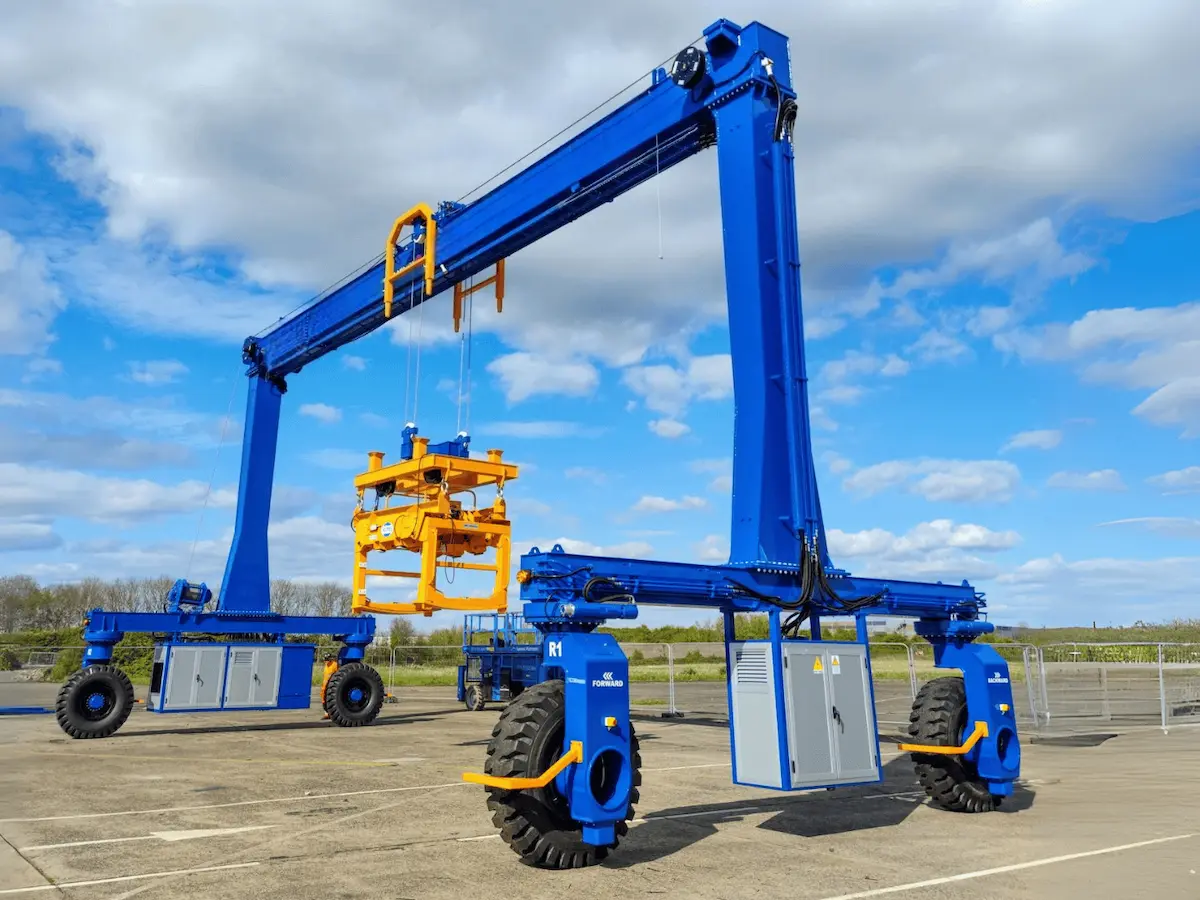
Single-beam rubber tyred gantry cranes are the simplest of the four types. They suit projects where “adequate” matters more than “redundant.”
●Main structure and working principle: One main box girder spans the gantry, with the hoist suspended below it. The trolley runs under the main girder, and tyre travel units allow trackless movement. An electric hoist or hydraulic winch drives lifting and travel. Load passes from hook to trolley, main girder, legs, and tyres.
●Design features and conditions: It weighs 30%–40% less than a comparable double-beam unit, lowering wheel pressure. Ground bearing requirements are therefore more relaxed. Torsional stiffness is naturally lower, so large spans make deflection critical. It suits moderate foundations, intermittent work, and mild load spectra.
●Capacity, span, and height effects: Common capacity is 5–40 t, span 10–25 m, and lift height 6–15 m. Beyond this range, cost rises quickly as girder sections and plates thicken.
●Applications: They handle medium loads, precast components, and general industrial yards. They are common for precast slabs, small beams, steel members, and molds. 12.5 t and 20 t units are widely used in precast and steel yards.
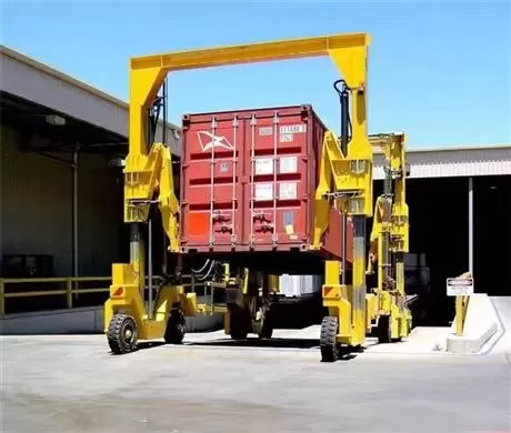
Double-beam rubber tyred gantry cranes solve cases where single-beam units “carry but cannot stay stable.”
●Structure and hoisting arrangement: Two parallel box girders connect through end beams to form the gantry. The trolley rides on top rails on both main girders. Hoisting can use one trolley and one winch, or two trolleys and two winches. The spreader or hook drops between the two girders. Top-mounted trolleys give more hook clearance than suspended single-beam arrangements.
●Load capacity and stability: The two girders share bending and torsional moments, so torsional stiffness is much higher. Eccentric loads and long loads are better distributed. Spans can reach 30 m or more, and capacity can be several times higher. The cost is higher dead weight, higher price, and greater ground bearing demand.
●Dual lifting points or multiple hoists: The gantry space naturally accommodates two hoisting units. The two hooks can work independently or synchronously. Precast girders and long steel structures often need two lifting points. Dual-trolley designs can lift long components with one machine. This reduces scheduling costs for two-machine coordination.
●Applications: They handle heavier precast girders, steel structures, large industrial components, and frequent handling. They typically lift 20 m and 32 m box girders in bridge precast yards. They also move steel coils, plates, and heavy machinery parts continuously.
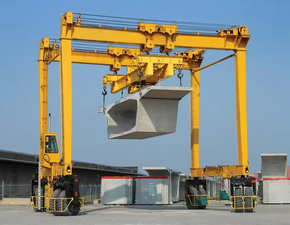
A-frame rubber tyred gantry cranes use narrow-top, wide-bottom legs instead of vertical legs. This geometry improves lateral stability for large spans and heavy duty.
●Structural layout: Two legs incline outward from main girder connection points, forming an A shape. The bottom wheelbase is wider than the top support spacing. Stiffener plates and transition arcs spread stress into the girder web. Loads split into vertical pressure and lateral components through inclined legs. The wide base lengthens the overturning moment arm and improves lateral resistance.
●Leg, crossbeam, and tyre travel design: A-frame legs resist wind and braking inertia well in height. Bottom crossbeams connect left and right legs, with tyre groups below. Large-span models often use multi-wheel equalizing suspension to distribute wheel pressure. The open A-frame has less wind area than closed box legs. This benefits open precast yards and bridge sites.
●Advantages for large spans and heavy lifts: Vertical-leg lateral stiffness drops quickly as span increases. A-frame inclined legs provide geometric lateral stiffness that does not fall linearly with span. Capacity can range from tens to hundreds of tonnes. With double beams and dual trolleys, very long precast components can be lifted integrally.
●Applications: They serve large precast yards, bridge construction, heavy equipment, and steel yards. They suit full-span box girders, large modules, and heavy steel yards.
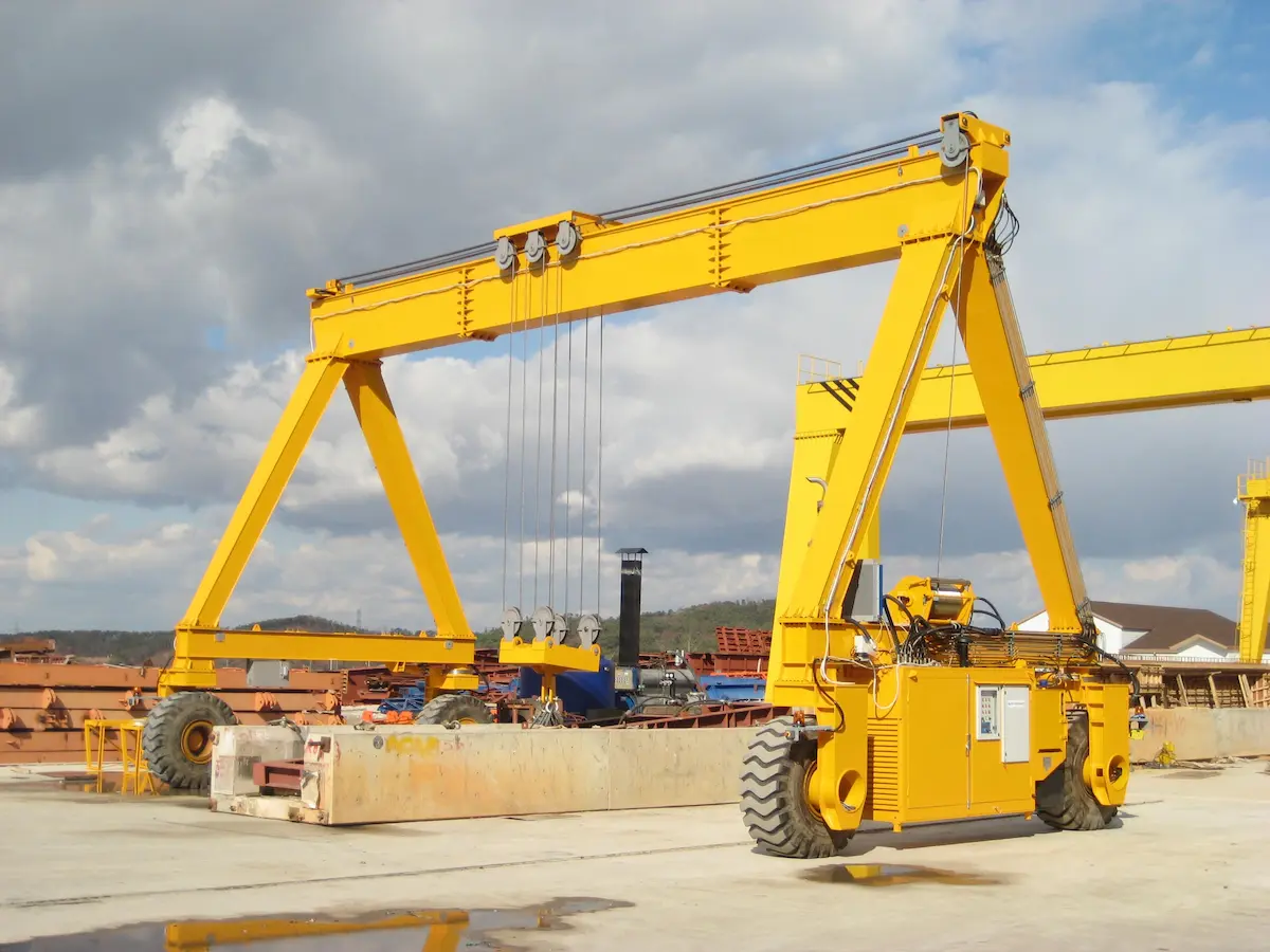
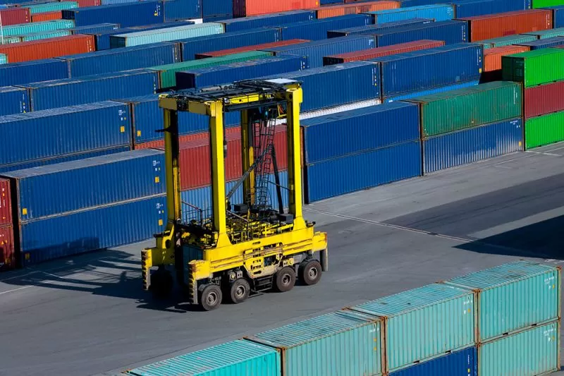
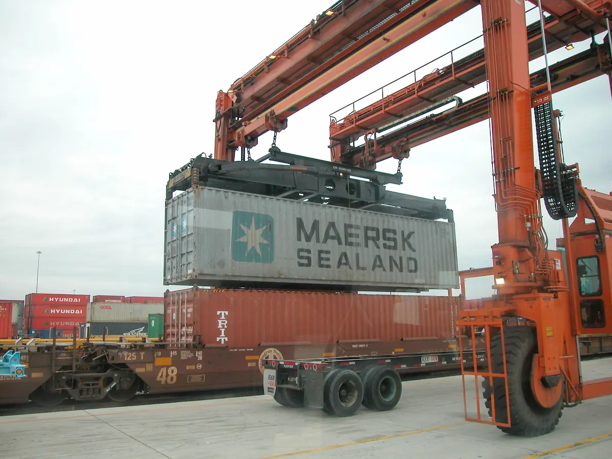
Container-specific rubber tyred gantry cranes are the most specialized type. Their clearance, spreader, and yard layout are reverse-designed around ISO container dimensions.
●Special gantry, trolley, and spreader: Gantry spans usually match yard block layouts; a standard span is 23.47 m. The trolley runs along the beam, with a telescopic spreader below the ropes. The spreader connects to corner fittings through twist locks. Its range covers 20 ft and 40 ft; some models adapt to 45 ft. It often has ±5° slewing for fine alignment.
●Container configurations: 20 ft containers can be handled singly under the spreader. 40 ft containers are the normal single-container lift. 45 ft containers need enough spreader travel and rated load coverage. Some RTGs use dual 20 ft spreaders to lift two boxes at once. Check that load under spreader covers the maximum gross weight. Rated classes include 35 t, 40 t, and 41 t.
●Yard design requirements: Stacking height determines lifting height. Common configurations are “stack three, pass four” and “stack five, pass six.” They need lifting heights of about 15.5–18.5 m. Trailer lanes are usually 3.5 m wide. The span must hold container rows and one working lane. Turning space must consider RTG radius and spreader swing. Lock these dimensions early; later changes are costly.
●Applicable scenarios: Port terminals, container yards, and multimodal logistics centers. The handling cycle and storage density of container-specific RTGs are designed for continuous container-logistics operations and are not suitable for use as general-purpose heavy-lift equipment.
Don’t compare this table horizontally by asking “which is stronger.” First identify your project bottleneck: capacity, span, aisle, or ground bearing. Single-beam and double-beam differ at the main girder level. A-frame mainly differs in leg geometry. Container-specific types specialize gantry clearance and spreaders. Do not mix concepts from different dimensions.
|
Type |
Structure |
Capacity/span |
Advantages |
Applications |
Notes |
| Single-beam RTGs | One main girder; hoist below | 5–40 t / 10–25 m | Light; low wheel pressure; simple | Medium loads; precast transfer; general yards | Weak torsion at large spans; lower economy |
| Double-beam RTGs | Two girders; trolley on top rails | 20–500 t / 15–50 m | High torsion; stable; dual hooks/trolleys | Heavy precast; steel; large parts; frequent work | Heavy; high wheel pressure; check ground and turning |
| A-frame RTGs | Narrow-top, wide-bottom legs; combined with girders | 20–500 t / 20–50 m | Geometric lateral stiffness; wind resistance | Large precast yards; bridges; heavy equipment | Leg form, not girder type; confirm combination |
| Container-specific RTGs | Special gantry; telescopic spreader | 35–41 t under spreader / 23.47 m | High density; 20′/40′/45′; continuous | Ports; container yards; intermodal centers | Lock stacking height, lane width, power point early |
Ranges in the table are common ranges, not capability limits. In real projects, double beams with A-frame legs and single beams with special spreaders are common. This table is better for initial screening. First exclude clear mismatches. Then take two or three remaining options to suppliers for parameter checks. This saves more time than debating “which is best” at the start.

Once the main structure is set, power, steering, and spreader configurations decide usability. Projects often detail main parameters but add spreaders and steering modes after ordering. Later changes cost money and delay schedules. This section covers these three categories.
●Diesel-powered type: This is the most traditional RTG power form. It has its own diesel generator set and needs no external cable or conductor rail. Relocation and cross-area work are flexible. Fuel consumption, noise, and emissions are relatively obvious. Use it cautiously in closed yards or sites with strict environmental rules. Check engine power against combined lifting and travel conditions. Do not look only at rated power.
●Diesel-electric hybrid type: A common design uses a diesel generator plus batteries or supercapacitors. It recovers energy during lifting and lowering. The storage unit supplies power at idle and light load. Fuel use and emissions are lower than pure diesel. It adds storage and control systems, so maintenance points increase. It suits sites needing relocation but lower energy use and emissions. Expect battery life and heat dissipation issues.
●Pure electric type: It uses cable reels, conductor rails, or rechargeable batteries. It gives zero emissions, low noise, and low energy cost. The yard must have enough power capacity and well-placed power points. Cable management must be smooth during relocation. Frequent cross-area work without charging reduces convenience. Align this with electrical engineers during planning. Do not wait until equipment arrives to find insufficient power points.
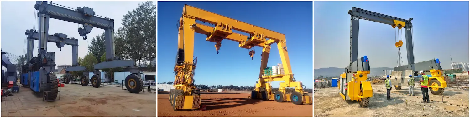
●Straight travel: This is the default travel mode along yard aisles. It looks simple, but aisle straightness, floor flatness, and tyre pressure affect deviation. This is especially clear over long travel distances.
●Front-wheel and rear-wheel steering: Front-wheel steering gives a relatively small rear swing. Rear-wheel steering gives a tighter turning radius but a different rear sweep area. Choose based on obstacles and turning space on both sides. Do not look only at turning radius.
●Lateral movement: Tyre groups deflect in the same direction, so the whole machine moves sideways. It suits alignment and edge work in narrow aisles. It requires good control systems and tyre wear management. Not all old yards suit frequent use.
●Diagonal movement and pivot turning: Diagonal movement and pivot turning need independent steering or special tyre groups. They are used for posture adjustment and direction change in limited space. Pivot turning causes high shear on ground and tyres. Check ground bearing and tyre configuration together. Do not count modes only from brochures.
●Determine steering configuration by aisle width and turning space: We usually suggest measuring clear aisle width, turning radius, and obstacle positions first. Then work backward to required steering modes. More modes mean higher control and tyre costs. Adequate is more practical than fully loaded.
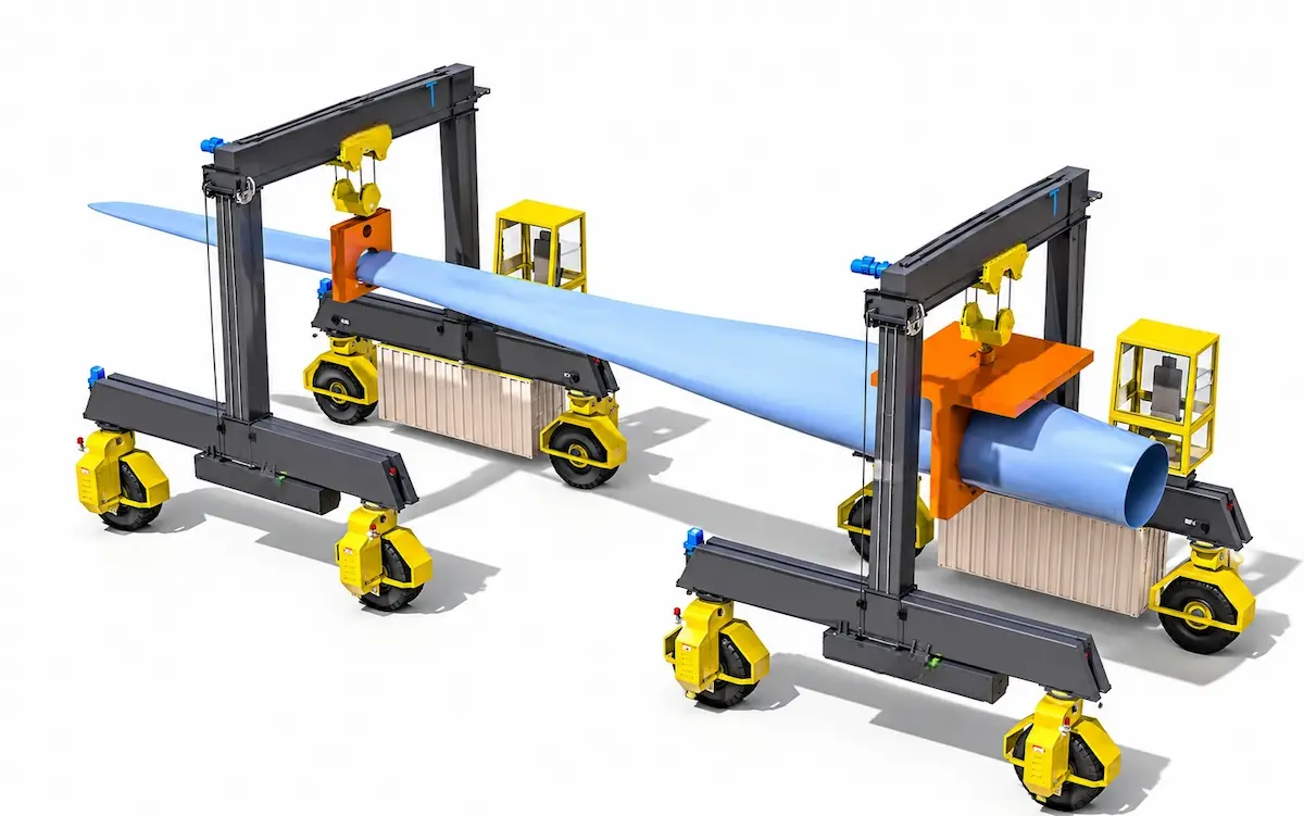
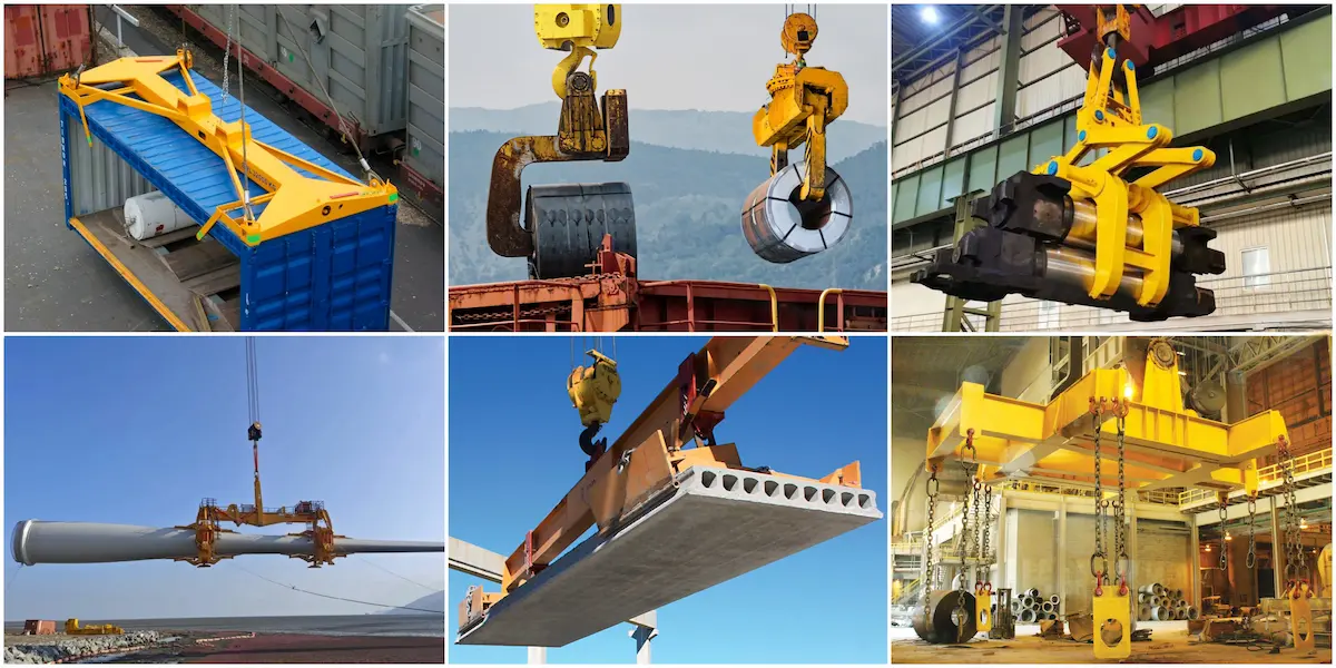
Spreader issues most often cause rework when the main machine is fixed but the spreader is added later. The table lists common configurations and selection notes by cargo type. Use it for early comparison.
|
Spreader type |
Cargo |
Structure/configuration |
Selection notes |
| Container-specific | 20/40/45 ft ISO containers | Telescopic spreader; twist locks; ±5° slewing; optional dual 20 ft | Check capacity under spreader; lock stacking height and lane width |
| Steel coil | Upright, horizontal, strip coils | C-hook, coil clamp, or lifting beam; coil diameter and surface protection | Check weight, diameter, clamping contact; upright and horizontal spreaders differ |
| Steel pipe | Long pipes, pipe rows, coated pipes | Lifting beam with slings, clamps, or hooks; multi-point balance and pipe protection | Pipe length and bending affect lifting points; state coating and end protection early |
| Wind blade | Wind blades and large composite parts | Blade clamp with posture adjustment and surface pads; center-of-gravity control | Supplier must check blade length, center of gravity, and allowed clamping zones |
| Concrete precast component | Precast slabs, girders, wall panels, segments | Lifting beam, equalizing beam, hooks, or vacuum pads; design for demolding and turning | Match demolding suction, center, and embedded lifting points; include turning cases |
| Long beam and large structure | Precast box girders, steel box girders, large modules | Equalizing beam with dual or multiple points; often synchronized with dual trolleys | Check dual-point synchronization and girder deflection; calculate eccentric long-load cases |
Notes in the table are not formalities. Spreader and main machine constrain each other. A heavy spreader reduces lifting capacity. More lifting points affect synchronization control. Clamping methods affect cargo surface protection. Put the spreader list and main parameters in one table for checking. This is less likely to miss items than separate quotations.
Use this table as an exclusion checklist, not a scoring sheet. Confirm capacity, span, and aisle constraints first; cross out mismatches; keep 2–3 options for supplier checks.
|
Selection dimension |
Confirm first |
Judgment points |
Common pitfalls |
| Cargo and spreader | Container, coil, pipe, or long beam? | Choose spreader first; include its weight in capacity | Machine fixed first; spreader cuts capacity |
| Rated capacity | Max single-piece weight? Include spreader and eccentric load? | Heaviest case + spreader + margin | Net cargo only; ignore rigging/eccentric load |
| Span and lifting height | Container rows/lanes? Stacking layers/loading height? | Span matches yard; height matches stacking and truck clearance | Single-beam economy drops at large spans; no spreader clearance |
| Ground bearing | Hardened layer thickness? Allowed wheel pressure? | Ask supplier for max wheel pressure; compare with ground design | Check total weight only; ignore single-wheel pressure |
| Aisle and steering | Clear aisle width? Turning radius? | Measure clear width/obstacles; then choose steering modes | Catalog radius only; ignore rear sweep/spreader swing |
| Work frequency | Shifts/day? Continuous or intermittent? | High frequency: A4–A8; medium-low: A3–A5 | High duty for low frequency; pay for unused margin |
| Power system | Stable supply? Emission/relocation needs? | Pure electric for power/emission cuts; hybrid/diesel for relocation | No power point for pure electric; ignore diesel emission limits |
| Lifecycle | Purchase, energy, tyres, maintenance? | Compare lifecycle cost, not quotation only | Purchase price only; ignore steering/tyre maintenance |
No “best solution,” only “matching solutions.” Extra configurations add maintenance points; adequate, maintainable, and upgradable is practical.
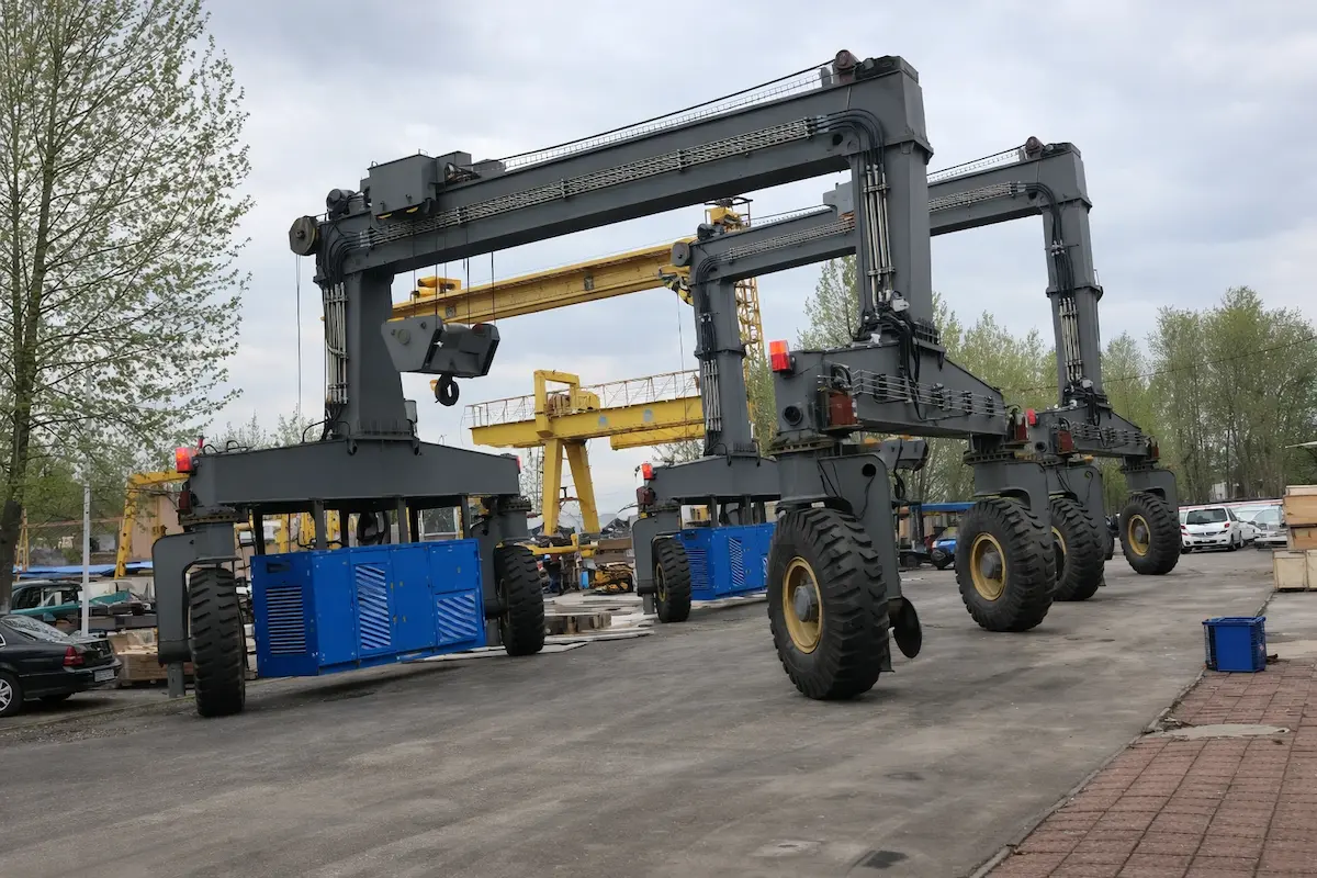
When browsing catalogues, it is easy to mistake “more configurations” for an advantage, but in real projects what matters is whether the basis is clear and the boundaries are well defined. For these HSCRANE points, we have tried to cite the relevant standards as well.
●Multiple structures: Single-/double-beam and A-frame/container gantry designs cover different tonnages and duties. Calculations follow FEM 1.001(1998) allowable stress and EN 13001-1:2015 Clause 4.2 proof; static/fatigue proofs follow EN 13001-3-1:2012 Chapters 5–6, providing regional acceptance bases.
●Eight steering modes: Straight, diagonal, lateral, and pivot modes improve site adaptability while meeting EN 15011:2011+A1:2014 Clause 4. More modes raise control/tyre maintenance costs; derive modes from measured aisle width.
●Dual-machine linkage: Handles long cargo lifting. Synchronization depends on load combination and duty class. ISO 4301-1:2016 Chapters 6–7 classify cycles/load spectrum; FEM 1.001 P0–P3 spectra support fatigue checks. Calculate linkage eccentric and synchronization loads separately—do not apply single-machine data.
●Flexible ground beam design: Ground beam/leg stability checks refer to FEM 1.004 (2004), covering buckling, overturning, and combined stresses. Travel alignment follows ISO 12488-1:2012 principles. Adjustable wheel pressure distribution does not mean “any ground works”; ground survey is required.
●Power and intelligent control: Control can use ISO 12482:2014 working-period monitoring to compare actual intensity with design classification for preventive maintenance. Power choice depends on supply and relocation frequency; higher standards are not always better.
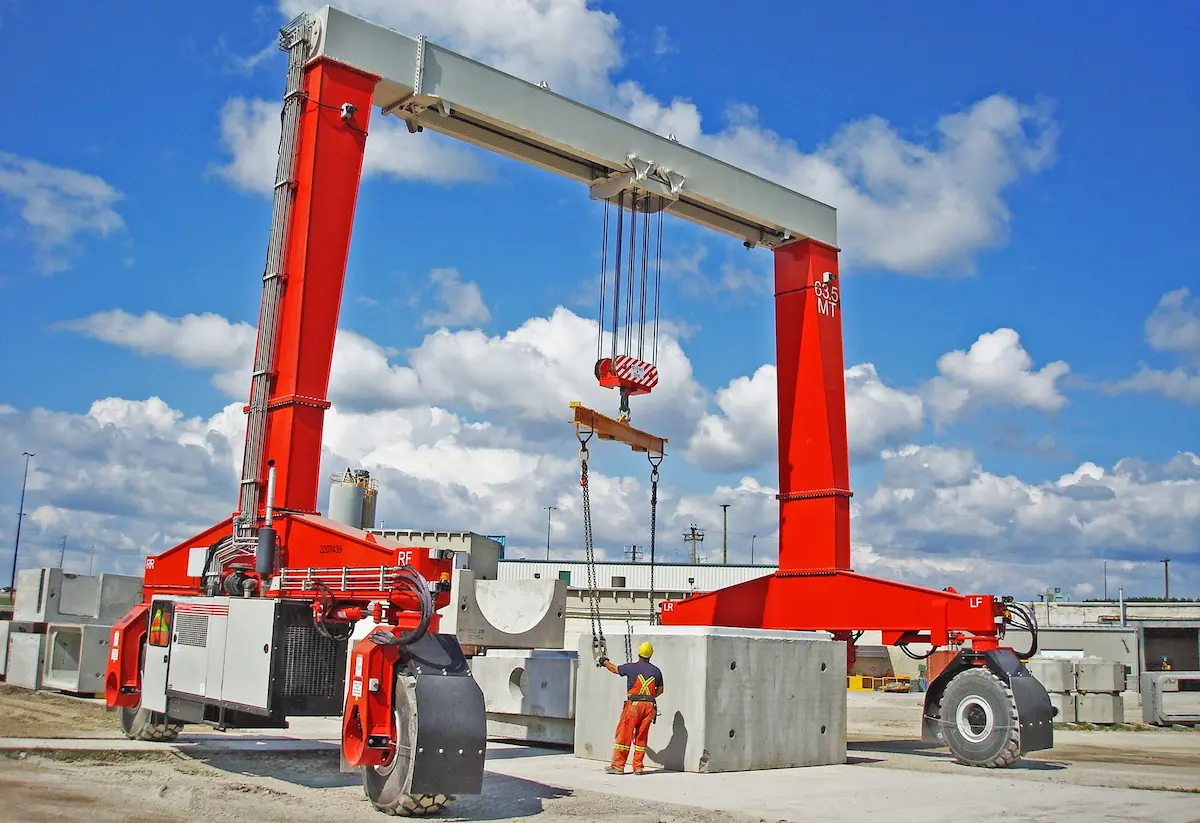
Writing cases should not give only tonnage and “customer is satisfied.” The two projects below use traceable delivery records. The Thai customer requested no disclosure of terminal operator information. Project location and technical parameters are in HSCRANE delivery files. The Indonesian customer name is also undisclosed by agreement. Equipment configuration and site conditions are documented.
●Customer background: A container terminal operator near Laem Chabang Port, Thailand. Rising throughput made existing yard equipment hard to match work pace. In 2026, the operator ordered one 60 t rubber tyred gantry crane from HSCRANE.
●Quantified configuration and operating data:
1.Rated capacity: 60 t under spreader. Span: 23.47 m. It covers six container rows and one trailer lane. Lifting height: 18.2 m, configured as “stack six, pass seven.”
2.Travel and steering: Eight wheels and four axles. It supports straight, diagonal, lateral, and pivot turning. Yard alignment is more flexible than common two-mode RTGs.
3.Environmental adaptation: For Thailand C5-M tropical marine corrosion, coating dry film thickness is ≥320 μm. Salt spray test exceeds 1,500 hours. Electrical cabinets use 316L stainless steel with IP66 protection.
4.Operating performance: After delivery, high-intensity operation lasted several months. Equipment availability stayed above 99.6%. Container turnover efficiency rose nearly 20%.
●Key takeaway: Note the “stack six, pass seven” lifting height and C5-M anti-corrosion configuration. If you look only at tonnage and span, you may miss tropical port coating and electrical protection needs.
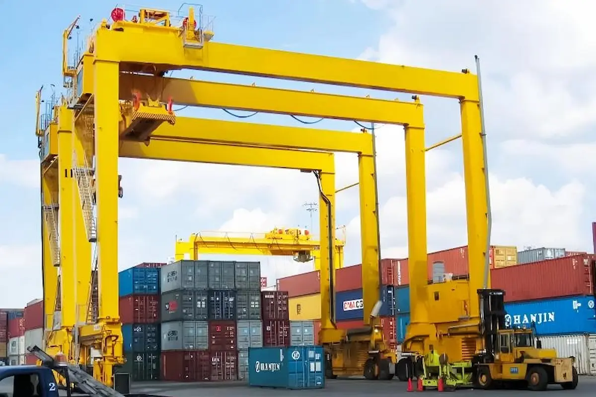
●Project background: An Indonesian highway bridge precast project. The customer needed a rubber tyred gantry crane for relocation between precast yard and bridge site. It also needed to lift precast beams directly. HSCRANE customized an 80 t class bridge construction configuration.
●Quantified configuration and site adaptation:
1.Rated capacity: 80 t, designed for single precast concrete beam weight. Lifting height is about 30 m. Span is 20 m. It covers main precast pedestal and beam storage layouts.
2.Travel system: Eight rubber tyres, diesel power, and at least 400 hp. It meets trackless relocation needs at bridge construction sites.
3.Working condition positioning: Bridge construction RTGs and container yard RTGs are different design approaches. The former values precast beam lifting point alignment and site passability. The latter pursues storage density and continuous cycles. Do not simply transfer by tonnage.
●Honest note: Public bridge construction RTG cases are fewer than port RTG cases. The core is the “80 t + 30 m height + 20 m span” set. It also shows diesel power matching at sites without electricity. If relocation frequency and ground bearing need finer checks, compare ground survey data with wheel pressure. This is more useful than reading a tonnage table.
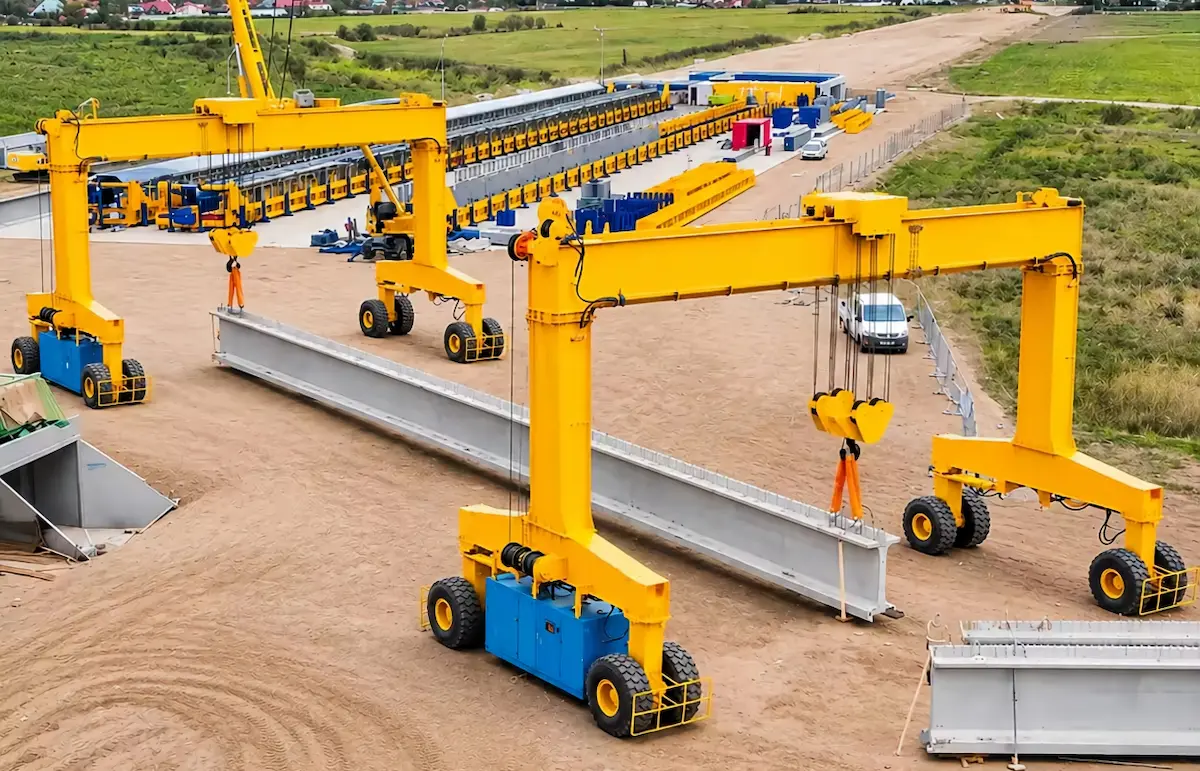
The core message is simple. Choosing rubber tyred gantry cranes is not about the prettiest parameters. It is about matching the site and cargo. Single-beam, double-beam, A-frame, and container-specific types each have limits. Power, steering, and spreader options each carry costs. We have seen projects choose oversized main units. Ground bearing and aisle width then fall short. Equipment arrives and cannot turn or bear pressure. We have also seen spreaders added later. Dual lifting point synchronization was not separately checked. Long loads then suffer eccentric loading. Instead of debating structure type, lock capacity, span, aisle, and ground data first. Let structures fit the data, not the reverse.
Buy a Custom Rubber Tyred Gantry Crane for Your Project
If you have a cargo list, site layout, or ground survey report, contact suppliers before bidding. Send these items to us for an initial configuration screening. We can exclude clearly mismatched options first. This saves time spent repeatedly changing parameters later.
[Contact HSCRANE Technical Team and Send Your Project Parameters]
Further Reading
After selection and configuration, tyre wear often appears first on site. It may relate to steering habits, wheel load distribution, or steering system alignment. This article starts from wear patterns and reviews steering and wheel load inspection ideas. It is suitable for reference after equipment commissioning.
Read full article: Why Do RTG Crane Tires Wear Unevenly? How to Inspect Steering and Wheel Loads
Q1: Is rated capacity just cargo weight?
No. Rated capacity means usable load below the spreader. Spreader, rigging, and eccentric loads reduce it. Give heaviest case, spreader weight, and eccentric factor for load checks. Do not report net cargo weight only.
Q2: Can double-beam RTGs work on thin hardened old yards?
Check wheel pressure first. Double-beam and A-frame units are heavier, wheel pressure is higher. Ask for maximum wheel pressure per case. Compare it with ground survey or design bearing. Use flexible or equalizing suspension if close. Choose single-beam or reinforce ground if far.
Q3: How do duty classes A3 and A6 affect RTG use?
They affect fatigue life and component margins, not lifting ability. ISO 4301-1:2016 classifies by cycles and load spectrum. A6 means higher frequency and heavier continuous duty. Low-frequency work with A6 buys unused margin. Match real cycles, not perceived busyness.
Q4: Are more steering modes always better?
No. Steering modes come from site constraints, not brochure scoring. Wide aisles need only normal steering. Lateral and pivot modes raise control and tyre costs. Eight modes suit old yards, narrow aisles, obstacles, edge alignment. Derive modes from measured aisle and turning radius.
Q5: Is there a universal power recommendation?
No. Pure electric needs stable power and low relocation frequency. Diesel offers relocation freedom but may face emission limits. Hybrid cuts fuel and emissions but adds maintenance points. Confirm power supply, relocation frequency, and emission rules first. Power form follows these conditions.
This document is for reference only. Specific operations must strictly comply with local laws and regulations and equipment manuals.